DTH Users Guide
This guide describes the most important features of the DTH-400 ATCA card and it’s RTM card.
Main card
Figure 1 shows the main ATCA board of the DTH-400. Three functionalities are implemented on this board: 1 DAQUnit (upper FPGA): implements DAQ functionality with up to 24 SLINK rockets and up to 5 100Gbps TCP/IP output links. 2 TCDS-2 interfaces: Interfaces to the TCDS-2 Captain and provides TCDS-2 clock and data stream via the backplane to sub-system blades. 3 Network switch: Provides network connectivity for all blades in the shelf via a network switch with up to two 10Gbps uplinks.
Figure 2 shows the front panel of the DTH-400.
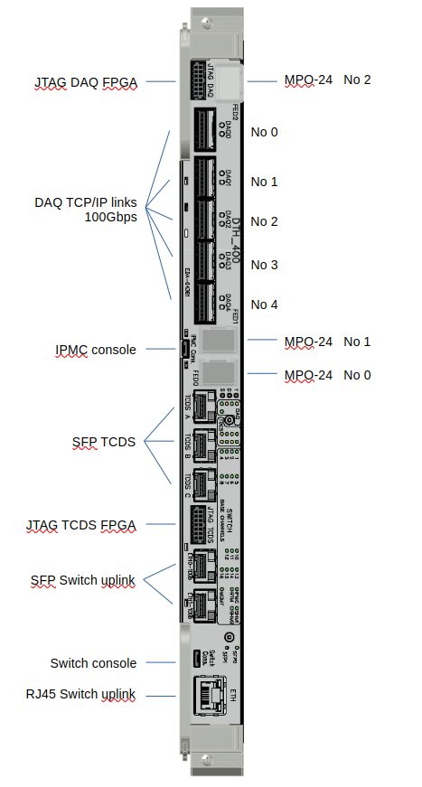
Next to the debugging JTAG connector on the top, you find a MPO-24 connector for 8 Slink connection .the 5 QSFP slots for the DAQ 100Gbps TCP/IP links.
On the bottom end of the front panel you see one RJ45 and 2 SFP optical connectors. One of these can be use as an uplink of the internal network switch (i.e. one of these can be connected to the “outside network”). However, be sure to only connect one of these three network connector since otherwise you create a network loop which will bring down the entire laboratory network (or more…)!
RTM card
IMPORTANT NOTE: Please do not insert jumpers and do not change the settings of the dip switches on the board. You could generate a short between powerlines together with a one-time fire works on your card, or you will make the card unusable (e.g. it does not boot anymore). You may only change the settings of J11 (see below) in case this is useful for you (normally this is not recommended or needed).
Figure 3 shows the RTM card. The RTM card houses the Zynq based system controller. A Kria controller is used for this embedded computer. In CMS it runs Alma Linux on top of a Petalinux kernel from Xilinx.
Lowest level bootloader code for the RTM card is contained in a on-board flash. This code reads a second stage bootloaded (U-BOOT) from the SD card which needs to be plugged into the foresee slot on the front-panel of the RTM card. This bootloaded then initiates a network boot procedure.
In principle it is also possible to boot from the SD card or from a NVMe SSD memory module on board of the RTM. However, this is currently not supported by the DAQ group.
The front panel of the RTM module is shown in Figure 4.
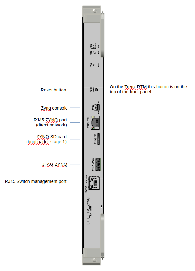
On the top a reset button can be used to hard-reset the controller.
A micro-usb port allows to connect a console to a computer. Once plugged into a linux computer a device /dev/ttyACM0 appears and can be attached to the minicom utility:
minicom -D /dev/ttyACM0
The console is then connected to the computer and can be used for debugging. Settings for the terminal are standard (in general the default settings of minicom are correct) : 115200 baud, 8NP.
**
You can access the ZYNQ console through the IPMC (for this, no cable should be plugged on the micro-usb connector).
> ipmitool -C 3 -I lanplus -H atca-lab40-r01-02p-ipmc.cern.ch -U "" -P "" -k gkey sol payload enable
> ipmitool -C 3 -I lanplus -H atca-lab40-r01-02p-ipmc.cern.ch -U "" -P "" -k gkey sol activate
atca-lab40-r01-02p = the name used by the IPMC clientID request
**
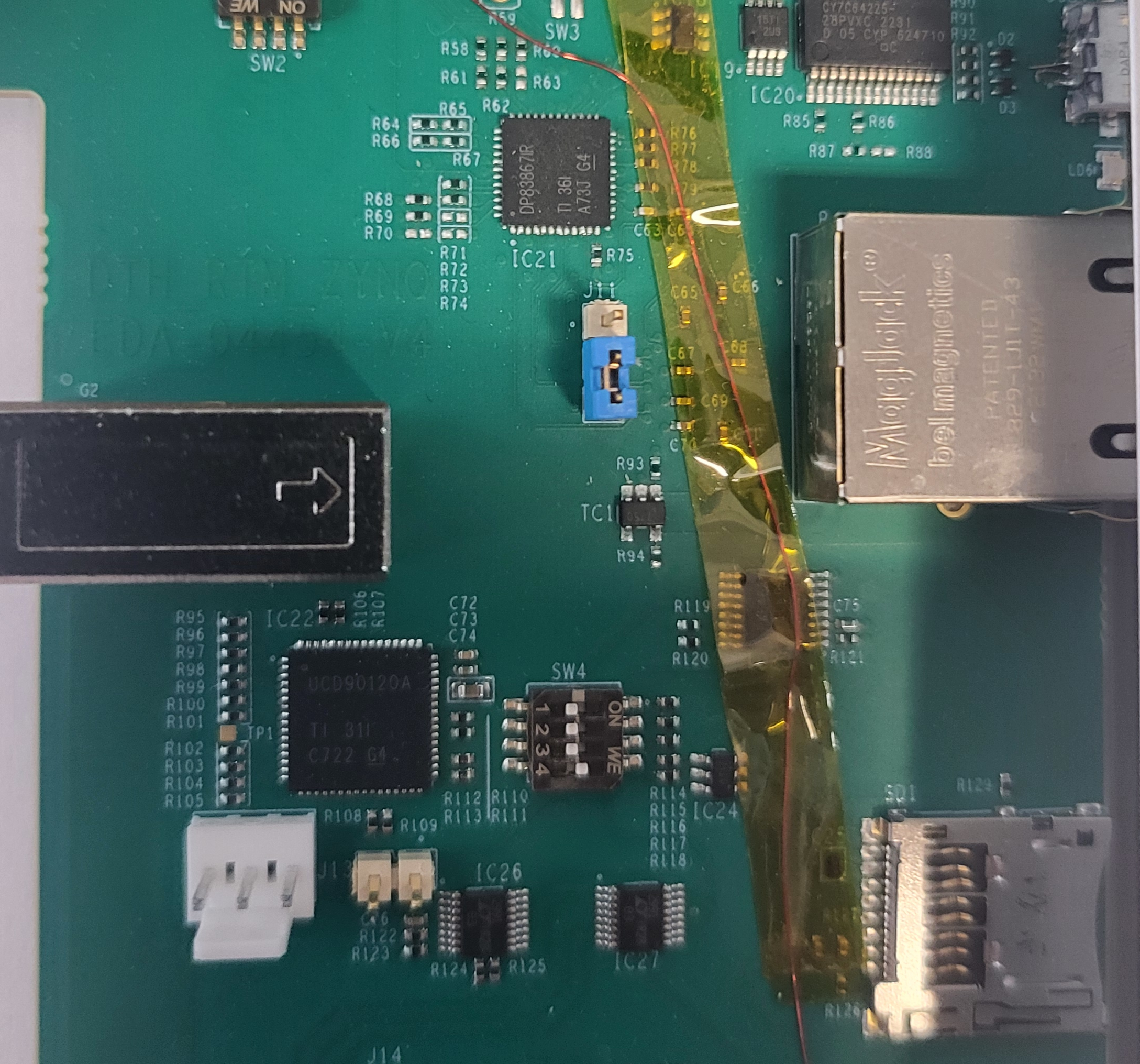
The front panel also houses two RJ45 connectors. The upper connector provides direct network connectivity to the Kria (bypassing the network switch on the ATCA blade.) To use this connector the jumper J11 needs to be set to the upper position. The default setting of this jumper (lower position as in the photo) is to provide network connectivity to the Kria via the network switch on the DTH-400. The photo below shows the location of the Jumper on the RTM board with it’s default setting.
The lowerRJ45 connector provides a connection to the management port of the network switch on the DTH-400. It is not needed for normal operation or setup.
Further Documentation
Website with technical information:
href="https://cms-daq-dth-p2.web.cern.ch/
Within this website link to a table with the preseries boards (containing the MAC addresses of all boards): Click on “Cards” and follow the link “Table” on that page:
https://cernbox.cern.ch/s/4geP9YUhFgkJfqO
Gitlab pages with instructions to install the network services to boot and run the system controller.
https://gitlab.cern.ch/hardware/phase2/network-services
Instructions to run the DAQ Unit controller:
https://cms-dth-daq.docs.cern.ch/
Instructions to install and run the TCDS-2 utilities on the System controller: